


DOCKER
WARIANTY URZĄDZENIA
Celem kompeksu jest ulepszenie - modernizacja właściwości istniejących urządzeń spawalniczych i także wybudowania swobodnie stosowanych celowych urządzeń spawalniczych i to w całym obszarze produkcji przemysłowej. Nowoczesny system sterowania z sterowaniem poprzez wyświetlacz dotykowy przynosi łatwe i intuitywne sterowanie wszystkich funkcji włącznie podłączonych pozycjonerów rolkowych i zrozumiały obraz sceny spawania z wysokim rozróżnieniem.
-
OBSERVER jest autonomiczny kompleks funkcyjny do kontroli i sterowania procesu spawania. Kopleks można użyć do dowolnych metod spawania i cięcia Plazmą, włącznie metody spawania pod topnikem SAW.
-
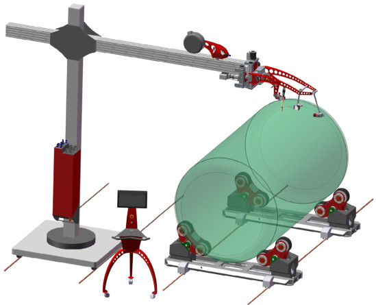
Konstrukcja mechaniczna jednostki krzyżowej CU10 jest rozwiązana jako spawany nośny korpus, który można umieszczyć na jakąkolwiek podstawę, albo docelową konstrukcję. Rama nośna jest wyposażona o prowadnice liniowe z suwem w osi Z +/- 100 mm, po której porusza się głowica palnika. Głowica palnika jest wyposażona o mechanizm obrotowy o 90°, na którym są umieszczone prowadnice osi X z suwem +/- 100 mm. Na osi X jest możliwe umieścić jednostkę oscylacji palnika PW 12 z suwem +/- 15 mm. Głowica palnika może być wyposażona o konzolę podajników drutu różnych konstrukcji i wymiarów i jest wyposażona nośnymi punktami dla trzymania kamery.
-
Kamera cyfrowa HST CREATIVE IRIS NICK jest namontowana na ramieniu odizolowanym, który może unosić także laser oznaczający. Obudowa kamery jest dwupłaszczowa z chłodzeniem elektroniki za pomocą powietrza. Jakościowy objektyw z ustawieniem przesłony i ostrzeniem jest chroniony szkłem i osłoną powietrzną, którą wytwarza powietrze wydmuchiwane z chłodzenia ciała kamery. Kamera wiernie odzwierciedla skupiony widok wprost do spawu a to bez filtrów dodatkowych. Softwarowe wylepszenie końcowego obrazu i system dostosowania aktualnej światłości sceny przynosi wierny i w pełni zrozumiały obraz i przy spawaniu dla kamery skomplikowanymi metodami jakie są metody MAG PULSE, nebo TIG AC. Przemyślane softwarowe przetwarzanie obrazu przynosi funkcję wirtualnego krzyża celowniczego i użytkownikiem określonym obszarze zainteresowania kiedy można obraz zjaśnić - ROI. ROI jest dalsza funkcja sterowana gestami dotykowymi na ekranie.
-
Kompleks jest sterowany z 19" TouchScreen wyświetlaczem o powierzchni szklannej wsadzony do stalowej designowej skrzyni, w której jest zarazem wsadzony komputer przemysłowy. LCD zapewnia dotykowe sterowanie funkcji kompleksu i zarazem służy do wyświeplania obrazu kamery w wdrążonym oknie.
Zalety podstawowe
√ Kompleks jest w pełni autonomiczny i można go samodzielnie zainstalować na dowolne urządzenie. Starsze urządzenie można łatwo zmodernizować.
√ Precyzyjne sterowanie osi ruchomych z dokładnością 0,1 mm, powtarzalna dokładność 0,2 mm i dużym suwem +/- 100 mm.
√ Możliwość obrotu prowadnic osi X umożliwia łatwo użyć urządzenie jednocześnie do spawania obwodowego i wzdłużnego.
√ Kamera cyfrowa zapewnia w pełni zrozumiały obraz jakiejkolwiek metody spawania, ustawialnym obszarze zainteresowania - ROI.
√ Możliwość podłączenia pozycjonerów rolkowych i ich sterowanie integrowanym softwarem sterującym.
√ Touch Screen LCD 19" wyświetla razem obraz kamery i elementy sterujące. Wspiera dotykowe sterowanie.
|
MOCE ROBOCZE |
WARTOŚĆ |
|
Prędkość obacania zbiornika na pozycjonerach rolkowych * |
0,74 - 369,0 cm/min |
|
Moment obrotowy na wałku wrzecion pozycjonerów rolkowych * |
Według wybranego pozycjonera |
|
Prędkość ruchu głowicy pionowy (Oś Z) |
0,01 - 150,0 cm/min |
|
Prędkość ruchu głowicy poziomy (Oś C) |
0,01 - 150,0 cm/min |
|
Maksymalne obciążenie głowicy palnika komponentami technologii spawaczej |
130 kg |
|
Maksymalne obciążenie głowicy oscylacyjnej plnikiem spawalniczym |
5 kg |
|
Obciążenie robocze ** |
24/7 |
| OSIE RUCHOWE | WARTOŚĆ |
|
Obrót pozycjonerów rolkowych (HST CREATIVE CARRIER) |
Programowo sterowana oś |
|
Ruch automatu po torach (oś Y) |
Programowo sterowana oś |
|
Ruch głowicy palnika pionowy (oś Z) |
+/- 100,0 mm, program. sterow. oś |
|
Ruch głowicy palnika pozoimy (oś C) |
+/- 100,0 mm, program. sterow. oś |
|
Ruch głowicy palnika obrotowy (oś R) |
90°, ręczna oś |
|
Oscylacja palnika |
+/- 20,0 mm, program. sterow. oś |
| TECHNOLOGIA SPAWANIA I STEROWANIA | WARTOŚĆ |
|
Odpowiednie metody spawania |
SAW, MIG/MAG, TIG, Plasma Weld |
|
Odsysanie palnika dla metoda SAW automatycznie * |
TAK |
|
Sygnalizacja braku topnika dla metody SAW * |
TAK |
|
Wymiar wyświetlacza dotykowego o przekątnej |
18,5" |
|
Kamerowy system wprost do patrzenia do łuku * |
Bez ograniczeń metod spawania |
|
Podłączenie źródła prądu systemem START/STOP |
TAK |
|
Programowo sterowanie podawanie drutu * |
TAK |
|
Stacjonarny cyfrowy sterownik "joystick" w miejscu obsługi |
Proporcjonalny |
|
ENERGIE, MEDIA A ŚRODOWISKO |
WARTOŚĆ |
|
Podłączenie z sieci |
3x400V 50/60 Hz |
|
Sprężone powietrze (suche, czyste) |
0,5 - 0,9 MPa |
| Charakterystyka umieszczenia na pozycji roboczej | Do montażu na inne konstrukcje |
| Stopień ochrony | IP 21 |
| Moc instalacyjna *** | |
|
ROZMIARY |
WARTOŚĆ |
|
Wysokość |
|
|
Szerokość |
|
|
Długość |
|
| Masa *** |
* Pozycja jest wybierana, albo istnieje więcej możliwości, które się różnią funkcją. Informacje są płatne dla najlepszego wyposażenia.
** 8/5 = obciążenie w jednej zmianie /// 16/6 = przemysłowe obciążenie /// 24/7 = obciążenie ciągłe.
*** Informacje nie można podać dokładnie, dlatego że są zależne na konkretnej konfiguracji. Podana jest maksymalna wartość efektywna.
... Dane techniczne mogą ulec zmianie bez wcześniejszego powiadomienia.
The information provided here describes the Control System as a whole with all its options, which may not be available for every positioner supplied, depending on its technological capabilities, and also depends on the selected configuration of the positioner. Therefore, it is always necessary to get acquainted with the positioner first, whether its technological possibilities, even with regard to the configuration you have chosen, support all the functions listed below or not. The information is an overview of the Control System's capabilities, not the positioner's, and does not purport to explain the individual elements in detail. This is mainly due to the difficulty in understanding some of the more complex functions or equipment. For details, please contact the HST CREATIVE sales department or the technical department.
√ Simple operation adapted to the operator's understanding of the Control System.
√ Clear standby mode with display of all setpoints via a large 19" display with reliable Touch Screen technology.
√ Convenient control of key functions in the standby mode of the Control System using touch controls to quickly select and change the working environment.
√ The internal MENU and settings are divided into graphical blocks for better orientation, which can be accessed directly from the standby mode.
√ Digitally controlled adjustment of welding parameters, oscillation, positioner rotation and all other key functions.
√ Precise operator positioning with 0.2 mm resolution via proportional joystick in Y, Z and W axes.
√ The possibility of selecting a suitable positioning unit and welding tower on which the welding will take place.
√ Modern computerised welding process control system with touch screen for scrolling through control modes, context menu and touch gestures.
√ Digital camera capture of the welding process with a wide range of parameter settings for image optimization, including ROI function. The captured image is displayed in the standby mode of the Control System with access to all image setting options.
√ Real-time measurement of the weldment temperature with display of the measured value in the standby mode of the control system.
√ Possibility to store your own welding programs and settings in the memory of the Control System using a programmable interface inside the system. The selected welding program is displayed in the standby mode of the Control System.
Control System Standby Mode

Technological functions of the Control System:
Welding settings:
-
Welding. Welding machine switching contact setting. In the automatic mode, the switching contact will be active, so the welding arc will be switched automatically by the machine every time after the start of the working cycle according to the set parameters of the WORKING PROGRAMME. In manual mode the welding contact is inactive, the welding arc switching must then be controlled manually by the operator on the welding control panel (Option: Automatic or Manual).
-
Direction of rotation. Setting the direction of rotation of the welded product (Option: Clockwise or Counterclockwise).
-
Diameter of the welded product. Setting the real diameter of the vessel is important so that the system correctly calculates the speed of rotation of the pulleys to achieve the desired progressive speed of rolling the vessel on the pulley units. Settings in cm range from 0.0 to 6500.0 cm. This function is only active when Automatic welding mode is selected.
-
Preheating. This function is used to melt the material well before starting the weld. Set the delay between the welding machine switching on and the start of rotation. The value is set in seconds with a precision of 0.1 sec in the range from 0.0 to 10.0 sec. The function is only active if Automatic welding mode is selected.
-
Angle of rotation. Defines the total angle by which the welded product is rotated. The limit value is 6500°. The function is only active if Automatic welding mode is selected.
-
Ending the weld. The point where the system switches off the welding contact to terminate the weld. Setting in angular degrees. The limit value is 6500°. The function is only active if Automatic welding mode is selected.
-
Welding JOB. Specific setting of welding parameters stored in the program memory of the welding power supply as a custom program that the machine calls up on the welder after starting the work cycle. Settings are possible in the range of 1 to 100. However, this functionality is only available if the communication between the machine and the welding source is controlled by a digital interface with the CanOpen protocol, otherwise basic analogue communication with START/STOP logic is available.
-
Temperature. Setting the limit value of the weldment temperature. The machine takes measurements during the welding process and when this limit temperature is reached, the system completes the current weld, but does not allow the welding process to continue with the next weld until the weld temperature has cooled below this set limit. The setting in degrees Celsius ranges from 0 to 250°C.
Pendel settings (Torch oscillation):
- Delay. Defines the time for which the pendling function will be inactive from the moment the welder is lit. The limit value is 10.0 s.
-
Left deflection. Defines how much deflection the torch will make from the center position to the left. Setting in millimetres with an accuracy of 0.1mm. The limit value is 20.0 s.
-
Right deflection. Defines how much deflection the torch will make from the center position to the right. Setting in millimetres with an accuracy of 0.1mm. The limit value is 20.0 s.
-
Frequency. Defines the frequency at which the torch will pendulum sideways. The setting is made in Hz, i.e. the number of oscillations per second. The limit value is 4.0 Hz.
-
Left delay. Defines the amount of time the torch will remain in the left position during the pendulum. The limit value is 20.0 s.
-
Right delay. Defines the amount of time the torch will remain in the right position during pendulum operation. The limit value is 20.0 s
Surface tracking:
-
Sensor for monitoring the position of the weld track in two axes Y and Z. It is a system that automatically copies the surface of the material and automatically adjusts the position of the welding torch above the material according to the surface properties of the welded product. This function operates fully automatically, no calibration or setting of input values is required. The system always monitors the position of the welding torch above the material from the starting position, i.e. the position from which welding started.
-
If the operator manually adjusts the position of the torch above the material to be welded in the Y and Z axes during welding (using the joystick or the arrows in the Control System), the weld track sensor will consider this newly set position as its default position from which it will measure the position above the material. Unless the operator is forced to adjust the welding torch position in any way during the welding process, the sensor will always start from its initial position from which the welding was started. The sensor for monitoring the welding track is therefore fully subordinate to the manual adjustment of the Y and Z axis position, which is fully within the operator's control.

Camera settings and image optimization:
-
The digital nature of the camera brings many useful features to optimize the image in every use situation. Of particular note is the ROI function (region of interest image selection) function, which increases the clarity of the welding scene to the maximum. Another important feature is the ability to display a virtual sighting cross.
- In addition to basic display optimization tools such as brightness and contrast, you can adjust Gamma Correction, which is a tool that adjusts the distribution of tones across the entire colour range (except black and white) to make the display more effective.
- The camera has a digital zoom, which together with the ability to zoom the camera up to a distance of 35cm from the welding allows sufficient image magnification.

Welding torch control by joystick on the control panel:
- The machine is equipped with a joystick, which can be used to simulate all the possibilities of setting the positions of the motion axes in real time, performed by standard arrow keys directly in the system.
- The joystick is fully proportional, i.e. depending on the degree of its deflection to the desired side, the movement of the element occurs at a proportional speed of its deflection in both axes. If the joystick is fully deflected to one side, the element will move at the maximum speed fixed in the FIRMWARE Control System. The system automatically calculates the displacement speed based on the given deflection as multiples of the base speed, which is fixed as a displacement of 0.2mm. This speed is continuously multiplied by the system until the limit value of the displacement given by the maximum deflection of the joystick is reached.
- The entire system reacts with a minimum response time of milliseconds, so it is a very precise system that, in conjunction with the camera system, gives the operator a feeling of maximum control over the welding process. The joystick is designed as the primary device for setting the positions of the motion axes, mainly because of its sensitivity and accuracy. Thus, during welding, the position of the welding torch should be tuned primarily by the joystick for best results. In the case of a joystick, it always depends on the environment chosen to determine which motion axes will be controlled by the joystick.


|

|
 |
 |
|||
 |
 |
 |
 |
|||
 |
 |
 |
 |