


Linia spawalnicza BWU 221.22
WARIANTY URZĄDZENIA
The purpose of the production line is heavy industrial work, even with a high hourly load. The machine can operate in manual and especially automatic mode with a high level of controlled functions, including functions to increase productivity. The production line control system offers uniquely sophisticated access to key functions, a clear user interface controlled by a touch screen, including communication with the welder and other key functions for setting welding parameters.
This is a bespoke solution that is only provided on a made-to-measure basis. Due to the complexity of the whole system and its parts, a very thorough consultation of the requirements is always necessary. The eventual feasibility and final technical solution of the project is provided as a special project solution and always exactly according to the parameters of the required products, the specific application or the customer's production program.
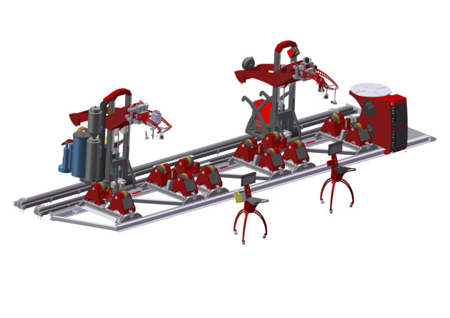
- The industrial production line BWU 221.22 is an equipment for welding of bulky weldments and large-capacity pressure vessels consisting of two separate workplaces, two welding towers and three pulley units with two positioners each. Each of the towers is equipped with a welding head, a cross unit and suitable welding technology. Included are positions to control the movement of the welding torch in the Y, Z and W axes - the Z axis for torch lift, the Y axis for its longitudinal movement and the W axis for torch extension. There is also a sensor for monitoring the position of the welding track in the two Y and Z axes. Depending on the welding technology used, the welding heads can be equipped with a pendulum unit, torch arm and head for fine-tuning the torch position. Both towers can weld simultaneously or separately within all three pulley units.
- The control of both towers includes a camera system with the possibility of fine-tuning the position of the torch in the Y, Z and W axes, this system is always superior to the sensor for monitoring the weld track. This means that if the operator manually adjusts the position of the torch above the material being welded in the Y and Z axes during welding, the weld track sensor considers this new position as its default position from which it measures the position above the material. Unless the operator is forced to adjust the position in any way during welding, the sensor always starts from its initial position from which welding was started.
- There is also a temperature sensor for measuring the temperature of the weldment. Temperature sensing is performed by an infrared sensor with laser targeting to better locate the measurement point. A limit value for the weldment temperature is set in the program. The system takes measurements during the welding process and when the limit temperature is reached, the system completes the current weld, but does not allow the welding process to continue with the next weld until the weld temperature has cooled below the set limit.
- Both welding towers have their own separate workstation with a Control System and a Windows-based industrial computer. The Control System's user interface is a 19" widescreen display with reliable Touch Screen technology and a glass surface that provides the operator with a visualisation of the advanced HST CREATIVE user environment, giving maximum control over the welding process and convenient set-up of all key functions required for circumferential welding. Touch scrolling through the control modes, context menu and the use of touch gestures underline the maturity of this system. Through the control system it is possible to conveniently monitor the welding process transmitted from the digital camera directly to the control system, as an embedded image in the control screen.
- Each workstation is equipped with a joystick, which can be used to simulate all the possibilities of setting the positions of the motion axes in real time. The joystick is fully proportional, i.e. depending on the degree of its deflection to the desired side, the movement of the given element occurs at a proportional speed of its deflection in the given Y, Z or W axes
- Welding programs can be saved in the system as unique work program settings for individual welding tracks. The number of positions for storing custom programs is not limited. If the temperature sensor measures a limit temperature of the weldment, the system will always complete the current welding program (weld), but the next program cannot be started until the weldment has cooled down below the set temperature limit.
- The rotation of the pulleys (rolling of the weldment) is solved in the form of three independent pulley units. Each of these pulley units consists of two pulley positioners and is equipped with a total of four drives, i.e. all pulleys are driven. Within each pulley unit the drives are synchronised. There are therefore a total of twelve drives, in three independent pulley units, i.e. each pulley unit has four drives synchronised together, which eliminates the tendency for drift of the product. These pulley units can be controlled (set) independently of each other within both workplaces, i.e. from both computers with the control system it is possible to set the parameters of all three pulley units independently.
- In the case of all sheave positioners it is possible to adjust the gauge of their transverse units to achieve the correct distance according to the diameter of the welded product for optimum load distribution. The transverse units are secured by a locking pin to lock the position. Within each pulley unit, the gauge of both positioners can also be adjusted according to the length of the product. The first positioner on the left is always fixed, i.e. it cannot be moved, the second positioner is movable along linear guides on the machine base after the pneumatic-mechanical brake is released. The positioners are also equipped with a system for holding the position of the product by means of laterally guided support pulleys, which secure the product against unwanted sideways movement during rolling, the so-called drift.
- The Control System also includes motion functions that are manually controlled in standby mode. These are the longitudinal movement of the welding towers in the X-axis along a linear guide and the lifting movement of the welding heads along the welding tower support, which is performed by a hydraulic unit.
- All motion axes are protected by their own limit switches to define the end positions, only the limit value of the lifting motion of the welding heads is protected by a hydraulic aggregate.
-
The production line can be equipped with the cold wire feeder HST CREATIVE CW 09. The cold wire feeder is fully controlled by the control system and brings maximum possibilities of setting the feeding parameters, including the reversal of the additional wire.
- A rotary positioner is also integrated, which has shared control with both towers. Welding on the rotary positioner is only available for the second tower. Welding with the first tower is not available for the rotary positioner because this tower is not structurally able to reach the rotary positioner. The positioner includes a main cabinet that integrates the complete wiring of the entire production line and the mechanics of the rotary positioner. The wiring is designed in the form of two pull-out boxes for better access in case of maintenance or service interventions.
Main benefits
√ The rigid construction of the two towers without mass vibrations transmitted to the welding zone eliminates mechanically caused welding defects.
√ Possibility of simultaneous use of two welding technologies (e.g. MIG/MAG + SAW).
√ Micro-slide axes without backlash with repeatable positioning accuracy to 0.2 mm, numerical position display.
√ Precise operator positioning with 0.2 mm resolution via proportional joystick.
√ Modern computerised welding process control system with touch screen and gesture control.
√ Digital camera recording of the welding process and an additional overview digital camera above the workstation for rough positioning.
√ Safe operator positioning at separate mobile control consoles.
|
WORKING PARAMETERS |
VALUE |
|
Nominal load of one complete roller unit (set of two roller positioners in total) |
7500,0 Kg |
|
Limit load of one complete roller unit (set of two roller positioners in total) |
9000,0 Kg |
|
Nominal load of one roller unit |
2150,0 kg |
|
Limit load of one roller unit |
3050,0 kg |
|
Maximal progress speed of roller unit |
200,0 cm/min |
|
Maximal rotation speed of rotary positioner |
2,0 rpm |
|
Duty cycle ** |
24/7 |
| WORKING DIMENSSIONS |
VALUE |
| Maximum diameter can be rotated between towers | 2150,0 mm |
| Maximum wheelbase of transverse units | 935,0 mm |
| Maximum gauge of positioners within one roller unit | 2234,0 mm |
| Height of the rotary positioner working plate | 1250,0 mm |
| MNOTION AXES | VALUE |
| Rotation of roller positioners | Controlled axis |
| Rotation of rotary positioner | Controlled axis |
| Longitudinal movement of wedling towers - axis X | Manually controlled axis in Standby mode |
| Stroke of the welding headso along the support of the welding tower | Manually controlled axis in Standby mode |
| Lenght of the welding heads hydraulic stroke | 800,0 mm |
| Speed of hydraulic stroke | 45,0 mm/sec |
| Longitudinal movement of the torch - axis Y | +/- 100,0 mm, Controlled axis |
| Stroke of the torch - axis Z | +/- 100,0 mm, Controlled axis |
| Pullout of the torch - axis W | +/- 75,0 mm, Controlled axis |
| Pendel axis (Torch oscilation) | +/- 20,0 mm, Controlled axis |
| Weld track monitoring by electro-magnetic sensor (monitoring of torch position) | axes Y a Z, Controlled axis |
| Camera system with the possibility of torch position correction by proportional joystick | axes Y, Z a W, Controlled axis |
| Adjustment of the welding arm basic position (3 joints) | Full range, manual axis |
| Precise adjustment of the torch position | +/- 15,0 mm, manual axis |
| Precise adjustment of the wire feeding | +/- 5,0 mm, manual axis |
| Joystick resolution | 0,2 mm |
| TECHNOLOGY OF WELDING AND CONTROLLING | VALUE |
| Suitable methods of welding | MIG/MAG, SAW, TIG, Plasma Weld, Laser |
| Electric current for DC transfered | 550A |
| Electric current for AC transfered | 450A |
| Maximum number of installed welding towers | 2 |
| Maximum number of installed roller units of two positioners each | 3 |
| Flux extraction for SAW method with automatic function | Yes |
| Signalling of lack of flux for the SAW method | Yes |
| Camera system for direct view into the weld | Yes |
| Weldment temperature measurement | Yes |
| Connection of welding source by START/STOP principle | Yes |
| Connection of welding source by UP/DOWN logic | Yes |
| Connection of welding source by CANOPEN digital Interface | Yes |
| Human Interface | 19" display with Touch Screen technology |
| Joystick for adjusting the torch position at the operator's place | Yes, proportional in axes Y, Z and W |
| Automatic torch height monitoring in axis Z - electromechanical sensor | Yes, axes Y a Z |
| Control system platform | MS Windows |
| Programmable feeding of the wire (0,6 / 0,8 / 1,0 / 1,2 / 1,6 mm)(Fe / CrNi / CrMo / Flux / Al / Cu) | Yes |
| Remote control | Yes |
| ELECTRIC POWER AND CONNECTING PARAMETERS | VALUE |
| Power supply | 3x400V/N/PE/50Hz |
| Pressure air (dry, clean) | 0,5 - 0,7 MPa |
| Design | Freestanding with the need to anchor |
| Level of IP | IP51C |
| Input power *** | 5500 VA |
| DIMENSSIONS | HODNOTA |
| Height *** | 3450,0 mm |
| Lenght *** | 12000,0 mm |
| Depth *** | 3500,0 mm |
| Weight *** | 4100,0 Kg |
* Optional item, or more versions are available which differs according to function. Mentioned parameters are valid for maximal options.
** 8/5 = lower loading in one duty period /// 16/6 = industrial loading /// 24/7 = non - stop loading
*** Parameters can not be provided with 100% correctness. Configuration of the machine must be taken into consideration. Mentioned parameters are valid for reaching maximal effective value.
...Subject to change the technical parameters without notice.
The information provided here describes the Control System as a whole with all its options, which may not be available for every positioner supplied, depending on its technological capabilities, and also depends on the selected configuration of the positioner. Therefore, it is always necessary to get acquainted with the positioner first, whether its technological possibilities, even with regard to the configuration you have chosen, support all the functions listed below or not. The information is an overview of the Control System's capabilities, not the positioner's, and does not purport to explain the individual elements in detail. This is mainly due to the difficulty in understanding some of the more complex functions or equipment. For details, please contact the HST CREATIVE sales department or the technical department.
√ Simple operation adapted to the operator's understanding of the Control System.
√ Clear standby mode with display of all setpoints via a large 19" display with reliable Touch Screen technology.
√ Convenient control of key functions in the standby mode of the Control System using touch controls to quickly select and change the working environment.
√ The internal MENU and settings are divided into graphical blocks for better orientation, which can be accessed directly from the standby mode.
√ Digitally controlled adjustment of welding parameters, oscillation, positioner rotation and all other key functions.
√ Precise operator positioning with 0.2 mm resolution via proportional joystick in Y, Z and W axes.
√ The possibility of selecting a suitable positioning unit and welding tower on which the welding will take place.
√ Modern computerised welding process control system with touch screen for scrolling through control modes, context menu and touch gestures.
√ Digital camera capture of the welding process with a wide range of parameter settings for image optimization, including ROI function. The captured image is displayed in the standby mode of the Control System with access to all image setting options.
√ Real-time measurement of the weldment temperature with display of the measured value in the standby mode of the control system.
√ Possibility to store your own welding programs and settings in the memory of the Control System using a programmable interface inside the system. The selected welding program is displayed in the standby mode of the Control System.
Control System Standby Mode

Technological functions of the Control System:
Welding settings:
-
Welding. Welding machine switching contact setting. In the automatic mode, the switching contact will be active, so the welding arc will be switched automatically by the machine every time after the start of the working cycle according to the set parameters of the WORKING PROGRAMME. In manual mode the welding contact is inactive, the welding arc switching must then be controlled manually by the operator on the welding control panel (Option: Automatic or Manual).
-
Direction of rotation. Setting the direction of rotation of the welded product (Option: Clockwise or Counterclockwise).
-
Diameter of the welded product. Setting the real diameter of the vessel is important so that the system correctly calculates the speed of rotation of the pulleys to achieve the desired progressive speed of rolling the vessel on the pulley units. Settings in cm range from 0.0 to 6500.0 cm. This function is only active when Automatic welding mode is selected.
-
Preheating. This function is used to melt the material well before starting the weld. Set the delay between the welding machine switching on and the start of rotation. The value is set in seconds with a precision of 0.1 sec in the range from 0.0 to 10.0 sec. The function is only active if Automatic welding mode is selected.
-
Angle of rotation. Defines the total angle by which the welded product is rotated. The limit value is 6500°. The function is only active if Automatic welding mode is selected.
-
Ending the weld. The point where the system switches off the welding contact to terminate the weld. Setting in angular degrees. The limit value is 6500°. The function is only active if Automatic welding mode is selected.
-
Welding JOB. Specific setting of welding parameters stored in the program memory of the welding power supply as a custom program that the machine calls up on the welder after starting the work cycle. Settings are possible in the range of 1 to 100. However, this functionality is only available if the communication between the machine and the welding source is controlled by a digital interface with the CanOpen protocol, otherwise basic analogue communication with START/STOP logic is available.
-
Temperature. Setting the limit value of the weldment temperature. The machine takes measurements during the welding process and when this limit temperature is reached, the system completes the current weld, but does not allow the welding process to continue with the next weld until the weld temperature has cooled below this set limit. The setting in degrees Celsius ranges from 0 to 250°C.
Pendel settings (Torch oscillation):
- Delay. Defines the time for which the pendling function will be inactive from the moment the welder is lit. The limit value is 10.0 s.
-
Left deflection. Defines how much deflection the torch will make from the center position to the left. Setting in millimetres with an accuracy of 0.1mm. The limit value is 20.0 s.
-
Right deflection. Defines how much deflection the torch will make from the center position to the right. Setting in millimetres with an accuracy of 0.1mm. The limit value is 20.0 s.
-
Frequency. Defines the frequency at which the torch will pendulum sideways. The setting is made in Hz, i.e. the number of oscillations per second. The limit value is 4.0 Hz.
-
Left delay. Defines the amount of time the torch will remain in the left position during the pendulum. The limit value is 20.0 s.
-
Right delay. Defines the amount of time the torch will remain in the right position during pendulum operation. The limit value is 20.0 s
Surface tracking:
-
Sensor for monitoring the position of the weld track in two axes Y and Z. It is a system that automatically copies the surface of the material and automatically adjusts the position of the welding torch above the material according to the surface properties of the welded product. This function operates fully automatically, no calibration or setting of input values is required. The system always monitors the position of the welding torch above the material from the starting position, i.e. the position from which welding started.
-
If the operator manually adjusts the position of the torch above the material to be welded in the Y and Z axes during welding (using the joystick or the arrows in the Control System), the weld track sensor will consider this newly set position as its default position from which it will measure the position above the material. Unless the operator is forced to adjust the welding torch position in any way during the welding process, the sensor will always start from its initial position from which the welding was started. The sensor for monitoring the welding track is therefore fully subordinate to the manual adjustment of the Y and Z axis position, which is fully within the operator's control.

Camera settings and image optimization:
-
The digital nature of the camera brings many useful features to optimize the image in every use situation. Of particular note is the ROI function (region of interest image selection) function, which increases the clarity of the welding scene to the maximum. Another important feature is the ability to display a virtual sighting cross.
- In addition to basic display optimization tools such as brightness and contrast, you can adjust Gamma Correction, which is a tool that adjusts the distribution of tones across the entire colour range (except black and white) to make the display more effective.
- The camera has a digital zoom, which together with the ability to zoom the camera up to a distance of 35cm from the welding allows sufficient image magnification.

Welding torch control by joystick on the control panel:
- The machine is equipped with a joystick, which can be used to simulate all the possibilities of setting the positions of the motion axes in real time, performed by standard arrow keys directly in the system.
- The joystick is fully proportional, i.e. depending on the degree of its deflection to the desired side, the movement of the element occurs at a proportional speed of its deflection in both axes. If the joystick is fully deflected to one side, the element will move at the maximum speed fixed in the FIRMWARE Control System. The system automatically calculates the displacement speed based on the given deflection as multiples of the base speed, which is fixed as a displacement of 0.2mm. This speed is continuously multiplied by the system until the limit value of the displacement given by the maximum deflection of the joystick is reached.
- The entire system reacts with a minimum response time of milliseconds, so it is a very precise system that, in conjunction with the camera system, gives the operator a feeling of maximum control over the welding process. The joystick is designed as the primary device for setting the positions of the motion axes, mainly because of its sensitivity and accuracy. Thus, during welding, the position of the welding torch should be tuned primarily by the joystick for best results. In the case of a joystick, it always depends on the environment chosen to determine which motion axes will be controlled by the joystick.

 |
 |
 |
 |
|||
 |