


Horizontal welding automat HMS 1750.02
MACHINE VARIANTS
Necesary choice
The green color indicates an element or the part that have to be installed to the machine in one of the offered variants already during its production and the machine cannot be forward into the operation without it, or order it.
Construction surcharge
Yellow coloring means an element or the part which have to be installed into the machine in some of the offered variants already during its production. In principle it is a device extending functionality.
Free equipment
The gray coloration indicates an element or the part which is possible to fit the machine at any time later. Assembly is possible by the end user. In principle it is an equipment which expands functionality.
Modern welding automat designed primarily for circumferential welding in hard industrial applications even with high hourly loading.
The overall concept of welding automat is greatly universal to be possible to use it for any circumferential welding and conditional longitudinal welding (not welding on copper underlay - for this purposes are designed our automats from AWL line). Welding automat focuses on the production of pressure and non-pressure vessels, machine parts, shafts, pipes, heat exchangers as well as welding of armature and other pipe or rod materials thanks to the hollow spindle. Welding automat can be used also for layered screw welding of horizontally clamped cylinder as well as for surface layered spiral welding on the plate in vertical positions. The functionality of layered screw welding is succesfully used for production of screw conveyors. The RCS 06 control system brings to the operator perfect functionality for full automation of circumferential welding, or layered welding.
-
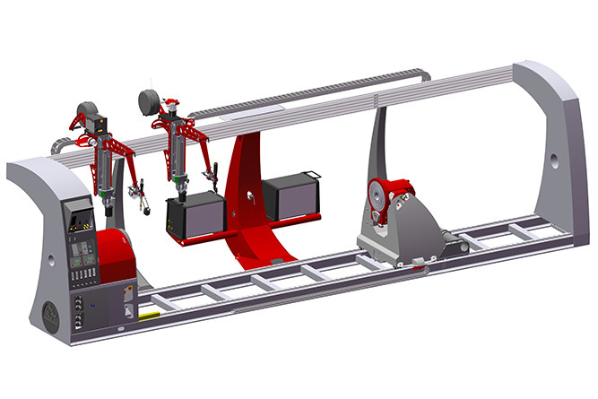
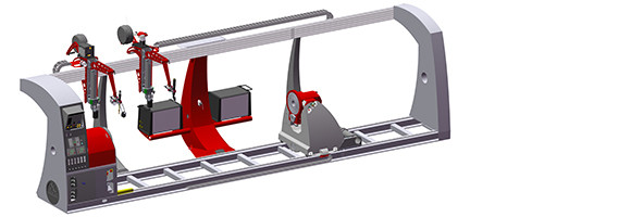
HMS LEADER 1750.02 is sophisticated horizontal welding automat of new generation designed primarily for circumferential welding with posibility of longitudinal welding and layered welding on products with maximum turning diameter of 1750 mm and maximum static loading of 5200kg for Mk.I and Mk.II versions and 5600Kg for HighPower version. The distance between the spindle flanges can be from 3500mm (basic length) to 10500mm.
- Automat can be supplied in three production versions - Mk.I, Mk.II, or HighPower. The spindle speed range for Mk.I version is set higher for rather lighter products of smaller diameter for rotation at higher speed however less torque is available. The Mk.II version has universal torque and spindle speed range for use with the standard sizes of welded products. The spindle speed range of HighPower version is set lower. However higher torque is available for use with bulkier products of larger diameters with weight closer to the maximum allowed loading of automat. Therefore the choice of version should depend on the expected use.
-
Mechanical construction of the highest quality is dimensioned for high loading. The self – supporting steel base construction of welding automat bears the main tower with integrated drive of the main spindle and control system on one side and the second supporting tower on other side. Between both towers there is longitudinal portal on which moveable torch heads are placed on precise roller bearings. The tailstock moves along base of welding automat on precise linear linnings. In addition we have solved the problem of welding fume extraction by integration of flexible air duct directly to the structure of the torch heads. Central support of main portal can include an effective system of cooling up to four welding torches.
-
Tailstock can be equipped with its own drive synchronized with the drive of the main spindle, both drives are backlash – free. Stepper motor spins precise planetary gearbox by which gear wheels with transverse teeth is driven. Main spindle as well as tailstock spindle has the same standardized flange for mounting of universal chuck 250mm, 315mm or 400mm.
-
Tailstock can be equipped with numerically controlled T axis so the tilting of the spindle of the tailstock in the range of 0 – 90° can be motorically controled. This concept advantage can be used for welding in specific positions or even by layered spiral welding also of larger desks. Pressure of the tailstock is designed as linear with blocking segment and pneumatical cylinder of 125mm, with standard stroke of 480mm (on request can be increased).
-
Torch head has servo drive with numerically controlled X axis for movement in longitudinal direction. The welding head is designed as version for one welding technology when welding automat can be equipped with two welding technologies simultaneously on two torch heads (in the case of two different welding technologies or two different type of welding sources consultation is required). If the technical requirements are met both torch heads can be equipped with an independent axis X servo drive on request (technical requirements consultation is required). The welding arm has stroke designed as numerically controlled Z axis with welding arm mechanically adjustable in three degrees of releasing and stroke of +/- 225 mm. At the end of the arm there is a precise support of the torch position with backlash-free adjustment in two axes +/- 15 mm and the possibility of rotation by 90 ° with position locking. Torch holder can be MIG, TIG or PLASMA WELD (others are on request).
-
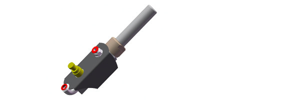
Welding arm can be equipped with special system for torch monitoring with an electro-mechanical sensor. This system is designed to automatically adjust the position the torch over the welded material during the welding process. Position setting takes place automatically based on data from the sensor using the movement axes of the welding torch. This system consists of special SW equipment and sensor for tracking the position of the weld path which is tactile probe that converts mechanical movement into a magnetic field sensed by an internal Hall probe. The sensor captures both height data (Z axis) and lateral position data (X axis).
-
The part of the configuration ca be also special system for welding the screw conveyors included the electromagnetic sensor for torch position monitoring as well as the software equipment which providing full functionality and all conceivable function for screw conveyors welding with mechanical adjustable roller support for rolling the product during welding.
- On request the welding automat can be equipped with controlled preheating system for heating the welded product to reach required temperature before welding, limit heating value is 600°C. In that case heating torch with thermometer and infrared sensor for temperature measurement will be placed on the second welding head, so the set is containing complete technology, construction elements and SW equipment. After reaching the required temperature the welding head smoothly forward to welding mode.
-
Welding automat can be equipped with cold wire feeder HST CREATIVE CW 09. The cold wire feeder is fully controlled by the RCS06 control system welding automat and brings to the operator the maximum possibilities of setting of the feeding parameters including the reversation of the feeding of the wire.
-
Significant simplification for the operator can be the equipment of the automat with special digital Remote Control Mighty Controller which increases the flexibility and variability above the basic configuration.
-
Automat is controlled by the excellent control system RCS 06 which provides all conceivable functions for circumferential welding, including accelerations and decelerations of rotary movement, control of the welding source with separate programming and advanced functions of regulation of welding power. The possibility of saving programs and creating program compilations underline the sophistication of the control system.

Using possibilities in a terms of weld type and technology
√ Circumferential welding with one or two identical torches. Multiple torches = adjustment.
√ Equipping with more different welding technologies (requires consultation).
√ Linear oscilation.
√ Longitudinal welding and oscilation with controlled X axis.
√ Tilting of the tailstock 0 - 90°, performing of fillet and position welds.
√ Layered screw welding with the possibility of controlled preheating.
√ Layered spiral welding with interpolation of rotation and torch displacement.
√ Control of the welding source by digital protocol Opencan or analog.
√ Feeding of the cold welding wire into the weld (TIG, PLASMA).
√ Protection of the root of the weld by controlled valve (max. 2 ways).
Main benefits
√ RCS 06 control system specially designed for circumferential welding tasks with high functional equipment.
√ Backlash-free drives with concept in the composition of Stepper motor > Planetary gearbox > Toothed gear wheels transmission > Spindle.
√ Through-hole spindles with standardized flanges for connecting a standard universal chucks.
√ Tailstock pressure in the longitudinal axis by pneumatic cylinder, movement along the precise linear guides.
√ Sophisticated torch arm with many degrees of releasing achieving high variability for internal and external welding.
√ Durable design with protection of sensitive parts, transmission of welding current by professional milled CuCrZr wiper.
|
WORKING PARAMETERS |
VALUE |
|
Maximal static loading (Mk.I / Mk.II / HighPower) |
5200,0 / 5200,0 / 5600,0 Kg |
|
Torque on the main spindle shaft (Mk.I / Mk.II / HighPower) |
1918,0 / 3198,0 / 4477,0 Nm |
|
Static angle clearance of the main spindle (loading not considered) |
- |
|
Torque on the tailstock shaft (synchronized drive with the main spindle)(Mk.I / Mk.II / HighPower) * |
1918,0 / 3198,0 / 4477,0 Nm |
|
Static angle clearance of the tailstock spindle (loading not considered) |
- |
|
Torque on the elevation shaft (T axis) * |
3931,2 Nm |
|
Speed range (Mk.I / Mk.II / HighPower) |
0 - 5,6 / 0 - 3,3 / 0 - 3,3 rpm |
|
Pressure of the tailstock towards the main spindle |
6000 N |
|
Duty cycle ** |
24/7 |
| DIMENSIONS |
VALUE |
| Maximal turning diameter | 1750,0 mm |
| Distance between the main spindle and tailstock spindle flanges * | 3500,0 - 10500,0 mm |
| Hole through the main spindle | 108,0 mm |
|
Diameter of the main spindle flange - recommended diameter of universal chuck * |
250,0 mm, 315,0 mm, 400,0 mm |
| Hole through the tailstock spindle | 108,0 mm |
| Diameter of the tailstock spindle flange - recommended diameter of universal chuck * | 250,0 mm, 315,0 mm, 400,0 mm |
| Tailstock working cylinder stroke (standard delivery, adjustment on request) | 480,0 mm |
| MOTION AXES | VALUE |
| Rotation of the main spindle | Controlled axis |
| Rotation of the tailstock spindle (synchronized with main spindle) * | Controlled axis |
| Elevation of the tailstock spindle (T axis) * | 0 - 90°, controlled axis |
| Longitudinal movement of the welding arm (X axis) | Full function, controlled axis |
| Stroke of the welding arm (Z axis) | +/- 225,0 mm, controlled axis |
| Adjustment of the welding arm basic position (3 joints) | Full function, manual axis |
| Precise adjustment of the torch position | +/- 15,0 mm, manual axis |
| Precise adjustment of the wire feeding * | +/- 5,0 mm, manual axis |
| TECHNOLOGY OF WELDING AND CONTROLLING | VALUE |
| Suitable methods of welding | MIG/MAG TIG, Plasma Weld, Laser |
| Electric current for DC transfered by spindle | 550A |
| Electric current for AC transfered by spindle | 450A |
| Connection of the welding source through START/STOP system | Yes |
| Connection of the welding source through the system of UP/DOWN logic | Yes |
| Automatic torch position monitoring on two axes X/Z- electro mechanic sensor (MIG/MAG, TIG) * | Yes |
| Preheating system for heating the weldment before welding (600°C) * | Yes |
| Automatic system and equipment for screw conveyors welding * | Yes |
| Connection of the welding source via digital interface CanOpen (CEBORA, LORCH) * | Yes |
| Programmable feeding of the wire (0,6 / 0,8 / 1,0 / 1,2 / 1,6 mm)(Fe / CrNi / CrMo / Flux / Al / Cu) * | Yes |
| Remote control * | Yes |
| POWER SUPPLY | VALUE |
| Power supply | 3x400V/N/PE/50Hz |
| Pressure air (dry, clean) | 0,5 - 0,7 MPa |
| Protective gases for welding | 1 independant way |
| Protective gases for root protection * | 1 independant way |
| Design | Stand desing, necessary to anchor |
| Level of IP | IP 51 C |
| Input power *** | - |
| DIMENSIONS | VALUE |
| Height *** | - |
| Length *** | - |
| Depth *** | - |
| Net weight *** | 3000 Kg |
* Optional item, or more versions are available which differs according to function. Mentioned parameters are valid for maximal options.
** 8/5 = lower loading in one duty period /// 16/6 = industrial loading /// 24/7 = non - stop loading
*** Parameters can not be provided with 100% correctness. Configuration of the machine must be taken into consideration. Mentioned parameters are valid for reaching maximal effective value.
...Subject to change the technical parameters without notice.
...The information given here describes entire RCS 06 control system with all possibilities which however may not be available for every machine depending on technological possibilities of specific machine. It also depends on selected machine configuration. Therefore is always necessary get acquainted with the specific machine at first whether its technological possibilities, even with regard to the configuration you have chosen, support all functions described below, or not. Informations given in here are the overview about possibilities of control system, not the machine and do not give explanation of individual components because of difficult comprehensibility of more complicated functions and equipment. For more details, please, contact the technical department or sales of HST CREATIVE.

Control system RCS 06
WORKING DATA
Basic choices
- Settings of the basic informations about the production (Rotary welding, linear welding, Layered screw or spiral welding)
- Settings of information about diameter of the product (Middle diameter of weld in mm)
- Assigning of the specific welding source to the specific welding head.
Axis...Rotation
- The direction of the rotation - Left or Right
- The delay of the rotation before the welding (time after the confirmation of the stable arc is sent from the welding source)
- First acceleration (settings of angle and value)
- Angle of rotation (maximal 720°, exactness 0,1°)
- Acceleration during the turning (settings of angle and value)
- Deceleration at the end of the turning for creating of the precise closing sequence and defect-free connection of beginning and end of the weld in a rotary welding (settings of angle and value)
- Spot welding (function enables to put regularly placed welded points along the circumference of welded product)
- Return to start point 0 (exact return to the start point - settings as shorter way or the whole way back)
Axis...Motoric
- In rotary mode of welding - the setting of the longitudinal welding position on the X Axis and its acting during the working cycle
- In longitudinal mode of welding - the setting of the welding position, the delay of activity after the welding process has started, the final time of welding, finishing of the sequence, the acting during the working cycle and radial position of the weld on the rotary axis
- The angle of tailstock's spindle 0- 90° (some of the machines). The fluent movement using the exact drive of tailstock's tilt or the logic of this function in case that the machine is equipped by the tailstock with pneumatically controlled stroke.
Axis...Of the torch
- The height of welding set by Z axis or the logic of controlling the pneumatical stroke of the torch.
- The position of welding set by another controlled axises of the arm of the torch (Z and K axis or the five - axis jointed arm).
Pendel
- The delay of the pendel after the confirmation of the stable arc is sent by the welding source.
- Frequency of the oscillatory movement (Hz).
- Right/Left divergence (in mm, separately for each side, exactness 0,1mm).
- Right/Left delay, delay in the middle (sets the linearity of pendeling, setting in sec.).
- The choice of programmed pendeling to some of the controlled axises.
The wire feeder (feeder CW 03, or CW 09 is needed)
- The delay of starting the wire feeding after the sign of the stable arc is sent by the welding machine (sec).
- Frequency of feeding. The frequency of changes in the speed of feeding of the wire (Hz).
- The Top (A) and Bottom speed (B) of feeding. Individual speeds (AB) of feeding are set separately (0 - 10m/min).
- The crumb. Setting of ratio between Top and Bottom speed of feeding (set in %).
- Oscillating wire reversation. It changes the direction of the wire feeding in the sense of setting of the bottom feeding speed (the wire burns out in batches with all of the benefits of this wire feed procedure
- Wire is pull in at the end of welding to prevent residual oxidation of the wire.
Controlling the source
- Control of the welding source depending on the selected system. Full MASTER digital control via HST CREATIVE OpenCan interface. Or simple analog controling via the REL analog element.
- Set of welding source switching ON angle (0 - 720°) and welding source switching OFF angle (max. 720°).
Forming gas
- Pre-blowing and after-blowing of forming gas into the torch for welding source number 1 and for welding source number 2.
- Pre-blowing and after-blowing of forming gas.
Another device
- Setting of digital remote control "Mighty controller"
- Control of the HST CREATIVE NICK 03 camera system (position setting and shooting parameters).
- High-precision control of welding position above the welded surface sensing by electromagnetic touch sensor.
- Welding data scanning and welding quality evaluation system.
- Connection of other external systems.
PROGRAMS - MEMORY BOXES
- The machine can memorize the own settings including the whole working cycle. There is a possibility to name, edit, copy, shift (199 free positions)
PROGRAMS - COMPILATION
- Programs safed in Memory boxes can be arbitrarily combinated into the functional lines and can create even the difficult working cycle. For example it is possible to weld like that (fully automated cycle with visual checking always with program changing - BREAK function):
Program 1 - The root layer of the weld done by TIG method without pendelling of the torch, speed range 45cm/min, without additional wire, power supply 72A.
Program 2 - The layer number two done by TIG method with pendelling of the torch and using the cold wire feeder, speed range 65 cm/min, power supply 160A.
Program 3 - The layer number three done by MAG PULSE method with pendelling of the torch, speed range 72cm/min, power supply 235 A.
QUICK OPTIONS
- Choice between automatic and manual mode at the touch of one button.
- "No Weld" function is available used to test the settings without welding.
- "Triangulation" button. A special button that is used to save the current positions of all controlled machine axes based on visual inspection by the operator. The machine records the visual input as the detected coordinates of the controlled axes.
DIRECT FUNCTIONS
- Forming gas test button (opens all of the gas valves when pressed).
- Welding torch manual tilt button.
- Button for manual closing of the pneumatic elements (for example tailstock pressing).
WELDED PARTS
- The machine is a universal and sophisticated production unit with the ability to weld any of the industrial production within the dimensional and weight limits of the machine. It is possible to perform rotary circumferential welds, fillet welds in the PA / PB position thanks to the tilting tailstock (only in the case of some of the machines) and it is also possible to perform full-fledged longitudinal welds (only the machines with controlled X axis).
- Typical is the production of pressure and non-pressure tanks from all materials with all of the methods of arc welding with the exception of the SAW method. Thanks to the high overall accuracy the machine enables welding of machine parts, flanges, shafts, heat exchangers, tube sheets.
- The machine is able to work in a layered screw welding mode (only the some machines) on the surface of the cylinder and also on the surface of the plate by the spiral layered welding tilted to the 90° (only the machines equipped with the tilting tailstock). Spiral layered welding has interpolated rotation and torch movement - change spindle rotation speed depending on the current diameter. The special software also provides the possibility of welding individual layers of layered welds (it uses a controlled Z axis of the torch stroke). It is also possible to equip the machine with the controlled preheating system of the welded part with digital surface temperature measurement.
TIPS FOR BETTER USE
- An excellent addition is the sophisticated Mighty Controler remote control. It is a freely programmable device by which is possible to control all of the necessary machine functions directly during the welding.
- The control system of the machine is well developed, it provides on-line information about the current rotation speed and the current progress speed. Operating is done using the standard multi-layer MENU.
- Software compilations provide perfect possibilities for fully automated production composite of many different welds.
- Double Torch versions does not restrict the users in the production of technologically complex products and aplications. One method can be used for welding of the root of the weld, another one can be used for the covering layers.
- The tilting tailstock significantly expands the usability of the machine by position welding at angles of 0 - 90°.
- Digital cold wire feeders provide precise welding results in the widest range of applications.
Basic configuration of the machine
C, D, E
Complete machine base ready for precise configuration
(( 1 )) Selection of tailstock type as driven or non-driven variant
(( 2 )) Selection of the torch welding arm and the functionality of torch holding elements
(( 3 )) Selection of technological accessories and improvements
(( 4 )) Selection of welding source and other accessories and complements
Basic equipment for automatization
1.1

Complete group of construction, linear guides and all energy pathways
(( √ )) Item is necessary for the intended function of the machine, NO ALTERNATIVE
(( Combination )) Selection of this item extends the working length of the machine. The MAXIMUM is 7
(( Options )) On request is possible to change the stroke of the tailstock pressure cylinder and its force
(( Condition )) Construction change which affects the design of the machine in an unchanging way
1.2
Structural accessory to increase stability of portal for the length between flanges over 5500mm
(( √ )) Additional supports to increase stability and strength of welding heads portal, NO ALTERNATIVE
(( Combination )) None
(( Options )) None
(( Condition )) Assembled and mounted directly at the production
1.3
Structural accessory serving as shelf for possible welding source - LEFT side as seen from the front
(( √ )) Welding source shelf LEFT, HAS AN ALTERNATIVE (1.4)
(( Combination )) With the second RIGHT shelf in case of using of two welding sources
(( Options )) Custom made dimension adjustment for specific welding source
(( Condition )) Assembled and mounted directly at the production
1.4
Structural accessory serving as shelf for possible welding source - RIGHT side as seen from the front
(( √ )) Welding source shelf RIGHT, HAS AN ALTERNATIVE (1.3)
(( Combination )) With the second LEFT shelf in case of using of two welding sources
(( Options )) Custom made dimension adjustment for specific welding source
(( Condition )) Assembled and mounted directly at the production
2.1
Complete tailstock without tilting of spindle and freely rotating spindle (flange 315mm, hole 108mm)
(( √ )) Item is necessary for intended function of the machine, HAS AN ALTERNATIVE (2.2)
(( Combination )) Selection of this item precludes the selecting of item (2.2), can be equipped with spindle drive
(( Options )) On request is possible to change the stroke of the tailstock pressure cylinder and its force
(( Condition )) Assembled and mounted directly at the production
2.2
Complete tailstock with controlled tilting of spindle and freely rotating spindle (flange 315mm, hole 108mm)
(( √ )) Item is necessary for intended function of the machine, HAS AN ALTERNATIVE (2.1)
(( Combination )) Selection of this item precludes the selecting of item (2.1), can be equipped with spindle drive
(( Options )) On request is possible to change the stroke of the tailstock pressure cylinder and its force
(( Condition )) Assembled and mounted directly at the production
3.1
Synchronized drive of the tailstock for Mk.I version which can be use for both variants of the tailstock
(( √ )) Item is optional to increase of the torque on the shaft of rotary axis, NO ALTERNATIVE
(( Combination )) This item can be use with both variants of tailstock, i.e items (2.1), or (2.2)
(( Options )) None
(( Condition )) Assembled and mounted directly at the production
3.2
Synchronized drive of the tailstock for Mk.II version which can be use for both variants of the tailstock
(( √ )) Item is optional to increase of the torque on the shaft of rotary axis, NO ALTERNATIVE
(( Combination )) This item can be use with both variants of tailstock, i.e items (2.1), or (2.2)
(( Options )) None
(( Condition )) Assembled and mounted directly at the production
3.3
Synchronized drive of the tailstock for HighPower version which can be use for both variants of the tailstock
(( √ )) Item is optional to increase of the torque on the shaft of rotary axis, NO ALTERNATIVE
(( Combination )) This item can be use with both variants of tailstock, i.e items (2.1), or (2.2)
(( Options )) None
(( Condition )) Assembled and mounted directly at the production
4.1
Additional welding arm with own support and controlled motoric stroke of torch in axis Z
(( √ )) This item is optional if two torches are necessary, NO ALTERNATIVE
(( Combination )) This item have to be further fitted with items (5.1), (5.2), or (5.3)
(( Options )) The maximum number of additional torch heads on one machine is one
(( Condition )) Assembled and mounted directly at the production
4.2
Second independent controlled X axis for longitudinal movement of additional torch head (4.1)
(( √ )) This item is optional, NO ALTERNATIVE
(( Combination )) Must be combined with item (4.1) and CanOpen digital controling (13.4)
(( Options )) None
(( Condition )) Assembled and mounted directly at the production
5.1

Cross head with precise adjustment of +/-15mm in axes X and Z and rotation of torch holder with fixation per each 30°
(( √ )) Item is necessary for intended function of the machine, HAS AN ALTERNATIVE
(( Combination )) This item have to be further fitted with item (ARM 2 TILT TORCH HOLDER)
(( Options )) None
(( Condition )) Can be installed in a simple operation without use of special tools
5.2

Cross head with precise adjustment of +/-15mm in axes X and Z, rotation of torch holder with fixation per each 30° and side turning possibility +/- 90°
(( √ )) Item is necessary for intended function of the machine, HAS AN ALTERNATIVE
(( Combination )) This item have to be further fitted with item (ARM 2 TILT TORCH HOLDER)
(( Options )) None
(( Condition )) Can be installed in a simple operation without use of special tools
6.1

Holder for MIG or TIG torch with tilting function at five fixed angles per each 15°
(( √ )) Item is necessary for intended function of the machine, NO ALTERNATIVE
(( Combination )) ARM 2 SLIDEMICRO is mounted on this part in the case of cold wire feeder is installed
(( Options )) Select a diameter of the torch, standard is 34mm. It have to always be a straight torch
(( Condition )) Can be installed in a simple operation without use of special tools
6.2

Holder for TIG torch with electromagnetic sensor for height tracking of the torch above the weldment
(( √ )) Can be used only in combination with numeric stroke of torch in Z axis, HAS AN ALTERNATIVE
(( Combination )) ARM 2 SLIDEMICRO is mounted on this part in the case of cold wire feeder is installed
(( Options )) Select a diameter of the torch, standard is 34mm. It have to always be a straight torch
(( Condition )) Assembled and mounted directly at the production
6.3

Holder for TIG torch with electromagnetic sensor for height tracking of the torch above the weldment
(( √ )) Can be used only in combination with numeric stroke of torch in Z axis, HAS AN ALTERNATIVE
(( Combination )) ARM 2 SLIDEMICRO is mounted on this part in the case of cold wire feeder is installed
(( Options )) Select a diameter of the torch, standard is 34mm. It have to always be a straight torch
(( Condition )) Assembled and mounted directly at the production
7.1
Feeder of cold wire 1,2 and 1,6 mm for TIG welding or PLASMA WELD
(( √ )) This item extends the functionality of the machine with effect to welding technology, NO ALTERNATIVE
(( Combination )) ARM 2 SLIDEMICRO have to be selected for proper function
(( Options )) None
(( Condition )) Assembled and mounted directly at the production
7.2

Cold wire feeding end element with the possibility of precise adjustment +/-5mm with cooled girder
(( √ )) Precisely made set feeds cold wire directly into the weld, NO ALTERNATIVE
(( Combination )) Mounted on the ARM 2 TILT TORCH HOLDER
(( Options )) None
(( Condition )) Can be installed in a simple operation without use of special tool
8.1

SET for solenoid control of forming gas - one way
(( √ )) Auxiliary element that improves the operation by switching the forming gas flow, NO ALTERNATIVE
(( Combination )) None
(( Options )) None
(( Condition )) Assembled and mounted directly at the production
8.2
Separate float flow meter with precise needle valve. Mounting on the surface through hole
(( √ )) Auxiliary equipment that improves the machine funcionality, bringing gas savings, NO ALTERNATIVE
(( Combination )) Mounted on the machine or can be mounted on a free-standing carrier, height 950mm
(( Options )) None
(( Condition )) Can be installed in a simple operation without use of special tools
9

Liquid cooling system for up to four welding torches integrated into the main portal support
(( √ )) Optional, can be used if welding source is not equipped with own cooling system, NO ALTERNATIVE
(( Combination )) None
(( Options )) None
(( Condition )) Assembled and mounted directly at the production
10
Fume exhausting SET integrating suction nozzle, piping and terminal element for connecting of exhausting
(( √ )) Auxiliary element for connecting of external exhausting system, NO ALTERNATIVE
(( Combination )) None
(( Options )) None
(( Condition )) Assembled and mounted directly at the production
11.1

Digital remote control with backlit display with the possibility of configuration of button functionality
(( √ )) Improves machine usability and facilitates direct welding control, NO ALTERNATIVE
(( Combination )) It is advisable to add a Holder for Mighty Controller
(( Options )) None
(( Condition )) Can be installed in a simple operation without use of special tools
11.2

Holder for remote control Mighty Controller freely mountable on any surface or the machine
(( √ )) Reduces the risk of damage to the Mighty Controller, NO ALTERNATIVE
(( Combination )) Used in conjunction with Mighty Controller
(( Options )) None
(( Condition )) Can be installed in a simple operation without use of special tool
11.3

Set of internal electronics and installation elements for connecting of another source to the machine
(( √ )) Extends functionality of machine with the parallel welding with additional source, NO ALTERNATIVE
(( Combination )) Can be used with any kind of welding source on the analog START/STOP principle
(( Options )) Up to four simultaneous sources can be connected on request
(( Condition )) Assembled and mounted directly at the production
11.4

Set of internal electronics and installation elements for digital connection of welding source
(( √ )) Allows full control of welding source, including program switching, NO ALTERNATIVE
(( Combination )) Can be used only with HST CREATIVE and CEBORA, limitedly LORCH (on request)
(( Options )) Two independent welding sources can be connected
(( Condition )) Assembled and mounted directly at the production
12.1

Software extending functions of the machine with londitudinal welding and pendel function in rotary mode
(( √ )) Item is optional to increase the software functionality of machine, NO ALTERNATIVE
(( Combination )) Can be used only with drive of torch head longitudinal movement - controlled axis X (4.1)
(( Options )) None
(( Condition )) Installed directly at the production
12.2

Software extending functions of the machine with layered screw
(( √ )) Item is optional to increase the software functionality of machine, NO ALTERNATIVE
(( Combination )) Can be used only with drive of torch head longitudinal movement - controlled axis X (4.1)
(( Options )) None
(( Condition )) Installed directly at the production
13
Special set of weldment preheating containing complete technology, construction elements and SW equipment
(( √ )) Item is intended for preheating the material before welding on set temperature, NO ALTERNATIVE
(( Combination )) None
(( Options )) Preheating torch can be selected for any gaseous fuel
(( Condition )) Construction change which affects the design of the machine in an unchanging way
Accessories
0.A

Three-jaw universal chuck with gears adjusted for welding, hole 78mm, weight 22.2kg
(( √ )) Chuck can be mounted on spindle flanges without transition elements, HAS AN ALTERNATIVE
(( Combination )) The chuck can be fitted with extended segments (custom made solution)
(( Options )) Other chucks can be choosed, but these have to be mounted using transition elements
(( Condition )) Can be installed in a simple operation without use of special tools
0.A

Three-jaw universal chuck with gears adjusted for welding, hole 108mm, weight 42.5kg
(( √ )) Chuck can be mounted on spindle flanges without transition elements, HAS AN ALTERNATIVE
(( Combination )) The chuck can be fitted with extended segments (custom made solution)
(( Options )) Other chucks can be choosed, but these have to be mounted using transition elements
(( Condition )) Can be installed in a simple operation without use of special tools
0.A

Three-jaw universal chuck with gears adjusted for welding, hole 144mm, weight 76,1kg
(( √ )) Chuck can be mounted on spindle flanges without transition elements, HAS AN ALTERNATIVE
(( Combination )) The chuck can be fitted with extended segments (custom made solution)
(( Options )) Other chucks can be choosed, but these have to be mounted using transition elements
(( Condition )) Can be installed in a simple operation without use of special tools
-

Vertically and transversely adjustable pipe support with pneumatic pressure and five pulleys
(( √ )) Mounted on the linear guide of the machine by means of rolling nests, NO ALTERNATIVE
(( Combination )) None
(( Options )) Functional ranges can be customized on request
(( Condition )) Can be installed in a simple operation without use of special tool
-

Vertically and transversely adjustable pipe support with independent arms for optimal tangential supporting
(( √ )) Mounted on the linear guide by means of rolling nests, HAS AN ALTERNATIVE (PARALLEL SUPPORT)
(( Combination )) None
(( Options )) None
(( Condition )) Can be installed in a simple operation without use of special tool
-

Vertically and transversely adjustable pipe support with arms clamped by a double-sided moving screw
(( √ )) Mounted on the linear guide by means of rolling nests, HAS AN ALTERNATIVE (SPATIAL SUPPORT)
(( Combination )) None
(( Options )) None
(( Condition )) Can be installed in a simple operation without use of special tool


Video - Aluminium welding |

Video - Screw conveyors welding |

Video - Digital camera IRIS NICK 3 |
 Welding automat HMS 1750.02 |
|||
 Welding automat HMS 1750.02 |
 Welding automat HMS 1750.02 |
 Welding automat HMS 1750.02 |
 Welding automat HMS 1750.02 |
|||
 Welding automat HMS 1750.02 |
 Welding automat HMS 1750.02 |
 Welding automat HMS 1750.02 |
 Screw conveyors welding |
|||
 Screw conveyors welding |
 Screw conveyors welding |
 Screw conveyors welding |
 Welding automat HMS 1750.02 |
|||
 Welding automat HMS 1750.02 |
 Welding automat HMS 1750.02 |
 Welding head with preheating system |
 Welding automat HMS 1750.02 |
|||
 Welding automat HMS 1750.02 |
 Welding automat HMS 1750.02 |
 Welding automat HMS 1750.02 |
 Welding automat HMS 1750.02 |
|||
 Welding automat HMS 1750.02 |
 Welding automat HMS 1750.02 |
 Welding automat HMS 1750.02 |
 Welding automat HMS 1750.02 |