


DOCKER system
MACHINE VARIANTS
The main purpose of this system is to improve the quality and possibilities of currently used welding devices and also to create the system of independantly used welding devices in the branch of industrial production. High-tech control system, which is operated throught the touchscreen display, brings easy and understandable controlling of all functions, including roller positioners.
-
DOCKER STATION is autonomous functional complex for controlling the welding process. This complex device can be used for any methods of welding and plasma cutting, including SAW method.
-
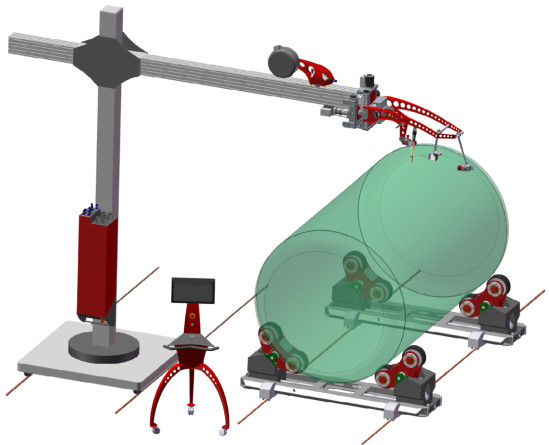
Mechanical construction of cross unit CU10 is designed as welded supporting frame that can be placed at any mounting points or construction. Supporting frame is equipped with linear bearing with the stroke of +/-100mm in Z axis along which the head torch is moved. The head of the torch is equipped with 90°movable mechanism on which X axis with the storke of +/- 100mm is placed. The pendel unit PW12 with the stroke of +/-20mm can be added to X axis. The torch head can carry support of cold wire feeder of any type of construction and of different dimensions and is equipped with mounting points for placing the camera.
-
Digital camera HST CREATIVE NICK 03 is mounted on separate support by which the laser can be carried as well. Camera consists of two layers equipped with cooling of electronics by the air. High quality object glass with adjustment of the screen and focusing is protected by protective glass that is changeable and also by the air screen that is created by waste air by which the device is cooled. Detailed view into the weld can be clearly provided by camera without using any extra filtration. The view taken by the camera is adjusted by software (including adjustment of lighting) and by this step clear and intelligible view is taken even by using for camera-complicated methods of welding MAG PULSE or TIG AC.
-
The NICK 03 camera is an advanced solution for visual checking of the welding process. No filters, no distortion, with negligible image delay, excellent intelligibility even with difficult welding methods. Digital image processing brings sophisticate functions which improve image quality and bring adaptation to the specific type of welding. The ability of storing of the record to the computer SSD drive underscores the high technical level of the device.
-
The NICK 03 is suitable for all of the types of welding including high-energy pulse welding using the MAG Pulse method. Likewise TIG DC welding with a large current level gradient is possible. TIG AC welding is detected precisely even with a high gloss of welded parts.
-
The computer of compact design is part of the camera case and processes the data flow for the industrial ETHERNET line which ensures excellent stability and is not susceptible to industrial interference from welding sources. The whole set have to be well cooled so it includes a sophisticated cooling system with air filtration. The lens has a glass cover which is easy for replace. The camera provides digital zoom with the possibility of zooming of the camera up to 35 cm from welding allows sufficient image magnification if necessary.
-
The essence of digital camera brings many useful features for image optimization in many situation of using. The ROI (the choice of the area of interest image selection) features deserves a special attention which increases uncluttery of welding scene to maximum of possible.
-
The device is controlled by 19” touchscreen display of glass surface which is fixed into steel design box in which is also industrial computer placed. By LCD touch controlling of functions is enabled including indicators of positions and parameters of welding and also enables to display camera imaging. The box, in which the display is fixed, is equipped with universal holder for mounting on the device and is possible to be equipped with ergonomic holder of controlling joystick with digital proportional function which is brought to the cross unit CU10.
-
Adding extending DOCK module can extend possibilities of function of this device. This module connects DOCKER STATION with roller positioners CARRIER (CLEVER type).
Main benefits
√ The whole complex is fully autonomous and can be mounted on any type of the device. It is the best way how to upgrade older devices.
√ Precise controlling of motoric axises with resolution 0,1mm, accuracy of 0,2mm and with stroke of both axises of +/- 100mm.
√ Possibility of rotation of wiring of X axis enables to use the device for rotary and longitudinal welding at the same time.
√ Digital camera with fully understandable focused view for any type of welding method, with adjustable ROI area of interest.
√ Possibility to add roller positioners and to control them by integrated controlling software.
√ Touch Screen LCD 19" which displays camera image, controlled elements and indicators of welding positions at the same time.
|
WORKING PARAMETERS |
VALUE |
|
Progress speed * |
0,74 - 369,0 cm/min |
|
Torque on shaft of roller positioners * |
According to type |
|
Vertical movement of torch head (Z axis) |
0,01 - 200,0 cm/min |
|
Horizontal movement of torch head (C axis) |
0,01 - 150,0 cm/min |
|
Maximal loading of torch head by options of welding technoloqies |
130 Kgs |
|
Maximal loading of pendel head by welding torch |
5 Kgs |
|
Duty cycle ** |
24/7 |
| MOTORIC AXISES | VALUE |
| Rotation of roller positioners (HST CREATIVE CARRIER) * | Controlled axis |
| Vertical movement of the torch head (Z axis) | +/- 100,0 mm, controlled axis |
| Horizontal movement of the torch head (C axis) | +/- 100,0 mm, controlled axis |
| Rotary movement of the torch head (R axis) | 90°, manual axis |
| Pendel of the torch | +/- 20,0 mm, controlled axis |
| TECHNOLOGY OF WELDING AND CONTROLLING | VALUE |
| Suitable methods of welding | SAW, MIG/MAG, TIG, Plasma Weld |
| Suction of flux for SAW method with automatic function * | Yes |
| Warning of running out of flux for SAW method * | Yes |
| Dimension of touchscreen in diagonal | 19" |
| Camera system NICK 03 for direct view into the weld * | SAW, TIG DC |
| Camera system NICK 03 for direct view into the weld * | Unlimited |
| Connection of welding device through START/STOP system | Yes |
| Controlled feeding of the wire * | Yes |
| Digital fixed control in the place of operation * | Proportional |
| POWER SUPPLY | VALUE |
| Power supply *** | 3x400V 50/60 Hz |
| Pressure air (dry, clean) * | 0,5 - 0,9MPa |
| Design | Mountable on constructions |
| Level of IP | IP 51 C |
| Input for installation *** | - |
| DIMENSIONS | VALUE |
| Height *** | - |
| Width *** | - |
| Depth *** | - |
| Net weight *** | - |
* Optional item, or more versions are available which differs according to function. Mentioned parameters are valid for maximal options.
** 8/5 = lower loading in one duty period /// 16/6 = industrial loading /// 24/7 = non - stop loading
*** Parameters can not be provided with 100% correctness. Configuration of the machine must be taken into consideration. Mentioned parameters are valid for reaching maximal effective value.
...Subject to change the technical parameters without notice.
The information provided here describes the Control System as a whole with all its options, which may not be available for every positioner supplied, depending on its technological capabilities, and also depends on the selected configuration of the positioner. Therefore, it is always necessary to get acquainted with the positioner first, whether its technological possibilities, even with regard to the configuration you have chosen, support all the functions listed below or not. The information is an overview of the Control System's capabilities, not the positioner's, and does not purport to explain the individual elements in detail. This is mainly due to the difficulty in understanding some of the more complex functions or equipment. For details, please contact the HST CREATIVE sales department or the technical department.
√ Simple operation adapted to the operator's understanding of the Control System.
√ Clear standby mode with display of all setpoints via a large 19" display with reliable Touch Screen technology.
√ Convenient control of key functions in the standby mode of the Control System using touch controls to quickly select and change the working environment.
√ The internal MENU and settings are divided into graphical blocks for better orientation, which can be accessed directly from the standby mode.
√ Digitally controlled adjustment of welding parameters, oscillation, positioner rotation and all other key functions.
√ Precise operator positioning with 0.2 mm resolution via proportional joystick in Y, Z and W axes.
√ The possibility of selecting a suitable positioning unit and welding tower on which the welding will take place.
√ Modern computerised welding process control system with touch screen for scrolling through control modes, context menu and touch gestures.
√ Digital camera capture of the welding process with a wide range of parameter settings for image optimization, including ROI function. The captured image is displayed in the standby mode of the Control System with access to all image setting options.
√ Real-time measurement of the weldment temperature with display of the measured value in the standby mode of the control system.
√ Possibility to store your own welding programs and settings in the memory of the Control System using a programmable interface inside the system. The selected welding program is displayed in the standby mode of the Control System.
Control System Standby Mode

Technological functions of the Control System:
Welding settings:
-
Welding. Welding machine switching contact setting. In the automatic mode, the switching contact will be active, so the welding arc will be switched automatically by the machine every time after the start of the working cycle according to the set parameters of the WORKING PROGRAMME. In manual mode the welding contact is inactive, the welding arc switching must then be controlled manually by the operator on the welding control panel (Option: Automatic or Manual).
-
Direction of rotation. Setting the direction of rotation of the welded product (Option: Clockwise or Counterclockwise).
-
Diameter of the welded product. Setting the real diameter of the vessel is important so that the system correctly calculates the speed of rotation of the pulleys to achieve the desired progressive speed of rolling the vessel on the pulley units. Settings in cm range from 0.0 to 6500.0 cm. This function is only active when Automatic welding mode is selected.
-
Preheating. This function is used to melt the material well before starting the weld. Set the delay between the welding machine switching on and the start of rotation. The value is set in seconds with a precision of 0.1 sec in the range from 0.0 to 10.0 sec. The function is only active if Automatic welding mode is selected.
-
Angle of rotation. Defines the total angle by which the welded product is rotated. The limit value is 6500°. The function is only active if Automatic welding mode is selected.
-
Ending the weld. The point where the system switches off the welding contact to terminate the weld. Setting in angular degrees. The limit value is 6500°. The function is only active if Automatic welding mode is selected.
-
Welding JOB. Specific setting of welding parameters stored in the program memory of the welding power supply as a custom program that the machine calls up on the welder after starting the work cycle. Settings are possible in the range of 1 to 100. However, this functionality is only available if the communication between the machine and the welding source is controlled by a digital interface with the CanOpen protocol, otherwise basic analogue communication with START/STOP logic is available.
-
Temperature. Setting the limit value of the weldment temperature. The machine takes measurements during the welding process and when this limit temperature is reached, the system completes the current weld, but does not allow the welding process to continue with the next weld until the weld temperature has cooled below this set limit. The setting in degrees Celsius ranges from 0 to 250°C.
Pendel settings (Torch oscillation):
- Delay. Defines the time for which the pendling function will be inactive from the moment the welder is lit. The limit value is 10.0 s.
-
Left deflection. Defines how much deflection the torch will make from the center position to the left. Setting in millimetres with an accuracy of 0.1mm. The limit value is 20.0 s.
-
Right deflection. Defines how much deflection the torch will make from the center position to the right. Setting in millimetres with an accuracy of 0.1mm. The limit value is 20.0 s.
-
Frequency. Defines the frequency at which the torch will pendulum sideways. The setting is made in Hz, i.e. the number of oscillations per second. The limit value is 4.0 Hz.
-
Left delay. Defines the amount of time the torch will remain in the left position during the pendulum. The limit value is 20.0 s.
-
Right delay. Defines the amount of time the torch will remain in the right position during pendulum operation. The limit value is 20.0 s
Surface tracking:
-
Sensor for monitoring the position of the weld track in two axes Y and Z. It is a system that automatically copies the surface of the material and automatically adjusts the position of the welding torch above the material according to the surface properties of the welded product. This function operates fully automatically, no calibration or setting of input values is required. The system always monitors the position of the welding torch above the material from the starting position, i.e. the position from which welding started.
-
If the operator manually adjusts the position of the torch above the material to be welded in the Y and Z axes during welding (using the joystick or the arrows in the Control System), the weld track sensor will consider this newly set position as its default position from which it will measure the position above the material. Unless the operator is forced to adjust the welding torch position in any way during the welding process, the sensor will always start from its initial position from which the welding was started. The sensor for monitoring the welding track is therefore fully subordinate to the manual adjustment of the Y and Z axis position, which is fully within the operator's control.

Camera settings and image optimization:
-
The digital nature of the camera brings many useful features to optimize the image in every use situation. Of particular note is the ROI function (region of interest image selection) function, which increases the clarity of the welding scene to the maximum. Another important feature is the ability to display a virtual sighting cross.
- In addition to basic display optimization tools such as brightness and contrast, you can adjust Gamma Correction, which is a tool that adjusts the distribution of tones across the entire colour range (except black and white) to make the display more effective.
- The camera has a digital zoom, which together with the ability to zoom the camera up to a distance of 35cm from the welding allows sufficient image magnification.

Welding torch control by joystick on the control panel:
- The machine is equipped with a joystick, which can be used to simulate all the possibilities of setting the positions of the motion axes in real time, performed by standard arrow keys directly in the system.
- The joystick is fully proportional, i.e. depending on the degree of its deflection to the desired side, the movement of the element occurs at a proportional speed of its deflection in both axes. If the joystick is fully deflected to one side, the element will move at the maximum speed fixed in the FIRMWARE Control System. The system automatically calculates the displacement speed based on the given deflection as multiples of the base speed, which is fixed as a displacement of 0.2mm. This speed is continuously multiplied by the system until the limit value of the displacement given by the maximum deflection of the joystick is reached.
- The entire system reacts with a minimum response time of milliseconds, so it is a very precise system that, in conjunction with the camera system, gives the operator a feeling of maximum control over the welding process. The joystick is designed as the primary device for setting the positions of the motion axes, mainly because of its sensitivity and accuracy. Thus, during welding, the position of the welding torch should be tuned primarily by the joystick for best results. In the case of a joystick, it always depends on the environment chosen to determine which motion axes will be controlled by the joystick.


|

|
 |
 |
|||
 |
 |
 |
 |
|||
 |
 |
 |