


Precise welding automat BWA 1500
MACHINE VARIANTS
Purpose of this machine is working in precise light components production or rod materials welding. Precise construction and factory adjustment of parallelism within tolerance of <0,2mm enables the welding of small and precise parts. High-quality drive guarantees perfect smoothness and constant rotation speed. RCS 06 control system brings to operator perfect functions for full automation of rotary welding production process, machine also has controlled output for switching the welding source arc.
This is a special solution which is provided only as custom made. Due to the complexity of the whole system and its parts very thorough consultation of requirements is always necessary. The final technical solution and possible feasibility of the project is provided as special project solution and always exactly based to the parameters of the required products, specific applications or the customer production program.
-
BWA 1500 device is precise rotary automat with maximum turning diameter of 150mm and static load capacity up to 15kg optimized for detailed welding even with two torches. Dimension between the spindles (maximum product length) is 1500mm. With regards to the expected use of machine the speed range is set on higher range because welding of rather lighter products with smaller diameter is expected.
-
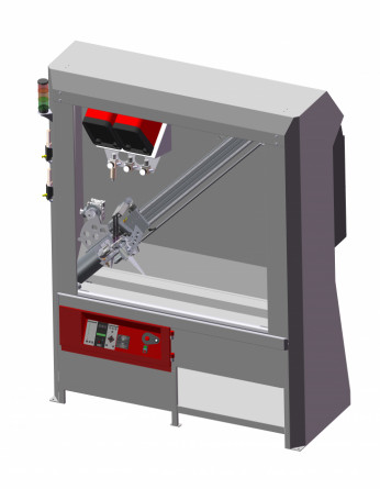
The machine is designed as completely enclosed device for complete separation the operator from the welding process with the recommendation to anchor the machine at the working place. The structure includes central beam which integrates main spindle with own drive and clamping elements. The tailstock which is optional element moves along the linear linning of the central beam. Basic structure of central beam also carries support providing stable platform for placing welding arm and the pneumatic clamping bezel block for clamping the product.
-
Tailstock can be fitted with own drive. In that case the drives of main spindle and tailstock are synchronized and solved as backlash-free. Stepper motor spins precise planetary gearbox with toothed belt.
-
Main spindle as well as tailstock spindle has standardized flanges with 28mm through hole with posibility of mounting 125mm universal chuck. However there is possibility to equip the machine with fully automated unattended clamping system which integrates pneumatic clamping elements of the main spindle and the tailstock spindle as special chucks with pneumatic jaws. These clamping elements for both spindles can be custom designed to meet the requirements of specific welding application.
-
Tailstock pressure is designed as linear with drawbar with precise mechanical adjustment of pressure force by nut and control lever or can be equipped with automated pneumatic pressure controlled by push button switch.
-
Central beam can be tilted manually in the range of 0 - 55°. The movement of the tilting is smooth using gearbox. Therefore is possible to set any position in order to optimize the welding process.
-
The machine is equipped with protective roller blind to separate operator from the welding process and with set of limit switches to define roller blind end and safety positions. Roller blind is controlled automatically by control system by switching the working cycle. Machine is also equipped with three-color light signaling device for simple indication of the production states in which the machine currently is. The machine can be transferred to the so-called service state.
-
The machine is equipped with powerful suction system for extracting welding fumes from the main box during welding. Inside the main box consoles for placing the welding sources and reduction valves for regulating the supplied shielding gas and compressed air to the pneumatic circuits of the machine are installed. Float flowmeters for shielding gases are also included.
-
Two-hand control device with integrated emergency stop switch is supplied with the machine to start the working cycle.
-
Welding arm is eqquiped with pneumatic stroke. At the end of the welding arm there is precise position support for up to two torches with backlash-free height adjustment in the range of +/- 15mm and the possibility of tilting the torches.
-
Significant simplification for the operator can be the equipment of the machine with special digital Remote Control Mighty Controller which increases the flexibility and variability of the basic machine.
-
Machine is controlled by excellent control system RCS 06 which provides all conceivable functions for rotary welding, including accelerations and decelerations of rotary movement, control of the welding source with separate programming and advanced functions of regulation of welding power. The possibility of saving programs and creating program compilations underline the sophistication of the control system.
-
The machine is designed for TIG welding.
Using possibilities in a terms of weld type and technology
√ Circumferential welding with one or two identical torches.
√ Tilting of central beam in the range 0 - 55°.
X Equipping with more different welding technologies.
X Linear and radial oscilation.
X Longitudinal welding and oscilation with controlled X axis.
X Layered screw welding with the possibility of controlled preheating.
X Layered spiral welding with interpolation of rotation and torch displacement.
√ Control of the welding source by digital protocol Opencan or analog.
Main benefits
√ RCS 06 control system specially designed for welding tasks with high functional equipment.
√ Backlash-free drives with concept in the composition of Stepper motor > Planetary gearbox > Toothed belt transmission > Spindle.
√ Through-hole spindles with standardized flanges for connecting a standard universal chucks.
√ Tailstock pressure in the longitudinal axis by pneumatic cylinder, movement along the precise linear guides.
√ Durable design with protection of sensitive parts, transmission of welding current by a professional milled CuCrZr wiper.
...The information given here describes entire RCS 06 control system with all possibilities which however may not be available for every machine depending on technological possibilities of specific machine. It also depends on selected machine configuration. Therefore is always necessary get acquainted with the specific machine at first whether its technological possibilities, even with regard to the configuration you have chosen, support all functions described below, or not. Informations given in here are the overview about possibilities of control system, not the machine and do not give explanation of individual components because of difficult comprehensibility of more complicated functions and equipment. For more details, please, contact the technical department or sales of HST CREATIVE.

Control system RCS 06
WORKING DATA
Basic choices
- Settings of the basic informations about the production (Rotary welding, linear welding, Layered screw or spiral welding)
- Settings of information about diameter of the product (Middle diameter of weld in mm)
- Assigning of the specific welding source to the specific welding head.
Axis...Rotation
- The direction of the rotation - Left or Right
- The delay of the rotation before the welding (time after the confirmation of the stable arc is sent from the welding source)
- First acceleration (settings of angle and value)
- Angle of rotation (maximal 720°, exactness 0,1°)
- Acceleration during the turning (settings of angle and value)
- Deceleration at the end of the turning for creating of the precise closing sequence and defect-free connection of beginning and end of the weld in a rotary welding (settings of angle and value)
- Spot welding (function enables to put regularly placed welded points along the circumference of welded product)
- Return to start point 0 (exact return to the start point - settings as shorter way or the whole way back)
Axis...Motoric
- In rotary mode of welding - the setting of the longitudinal welding position on the X Axis and its acting during the working cycle
- In longitudinal mode of welding - the setting of the welding position, the delay of activity after the welding process has started, the final time of welding, finishing of the sequence, the acting during the working cycle and radial position of the weld on the rotary axis
- The angle of tailstock's spindle 0- 90° (some of the machines). The fluent movement using the exact drive of tailstock's tilt or the logic of this function in case that the machine is equipped by the tailstock with pneumatically controlled stroke.
Axis...Of the torch
- The height of welding set by Z axis or the logic of controlling the pneumatical stroke of the torch.
- The position of welding set by another controlled axises of the arm of the torch (Z and K axis or the five - axis jointed arm).
Pendel
- The delay of the pendel after the confirmation of the stable arc is sent by the welding source.
- Frequency of the oscillatory movement (Hz).
- Right/Left divergence (in mm, separately for each side, exactness 0,1mm).
- Right/Left delay, delay in the middle (sets the linearity of pendeling, setting in sec.).
- The choice of programmed pendeling to some of the controlled axises.
The wire feeder (feeder CW 03, or CW 09 is needed)
- The delay of starting the wire feeding after the sign of the stable arc is sent by the welding machine (sec).
- Frequency of feeding. The frequency of changes in the speed of feeding of the wire (Hz).
- The Top (A) and Bottom speed (B) of feeding. Individual speeds (AB) of feeding are set separately (0 - 10m/min).
- The crumb. Setting of ratio between Top and Bottom speed of feeding (set in %).
- Oscillating wire reversation. It changes the direction of the wire feeding in the sense of setting of the bottom feeding speed (the wire burns out in batches with all of the benefits of this wire feed procedure
- Wire is pull in at the end of welding to prevent residual oxidation of the wire.
Controlling the source
- Control of the welding source depending on the selected system. Full MASTER digital control via HST CREATIVE OpenCan interface. Or simple analog controling via the REL analog element.
- Set of welding source switching ON angle (0 - 720°) and welding source switching OFF angle (max. 720°).
Forming gas
- Pre-blowing and after-blowing of forming gas into the torch for welding source number 1 and for welding source number 2.
- Pre-blowing and after-blowing of forming gas.
Another device
- Setting of digital remote control "Mighty controller"
- Control of the HST CREATIVE NICK 03 camera system (position setting and shooting parameters).
- High-precision control of welding position above the welded surface sensing by electromagnetic touch sensor.
- Welding data scanning and welding quality evaluation system.
- Connection of other external systems.
PROGRAMS - MEMORY BOXES
- The machine can memorize the own settings including the whole working cycle. There is a possibility to name, edit, copy, shift (199 free positions)
PROGRAMS - COMPILATION
- Programs safed in Memory boxes can be arbitrarily combinated into the functional lines and can create even the difficult working cycle. For example it is possible to weld like that (fully automated cycle with visual checking always with program changing - BREAK function):
Program 1 - The root layer of the weld done by TIG method without pendelling of the torch, speed range 45cm/min, without additional wire, power supply 72A.
Program 2 - The layer number two done by TIG method with pendelling of the torch and using the cold wire feeder, speed range 65 cm/min, power supply 160A.
Program 3 - The layer number three done by MAG PULSE method with pendelling of the torch, speed range 72cm/min, power supply 235 A.
QUICK OPTIONS
- Choice between automatic and manual mode at the touch of one button.
- "No Weld" function is available used to test the settings without welding.
- "Triangulation" button. A special button that is used to save the current positions of all controlled machine axes based on visual inspection by the operator. The machine records the visual input as the detected coordinates of the controlled axes.
DIRECT FUNCTIONS
- Forming gas test button (opens all of the gas valves when pressed).
- Welding torch manual tilt button.
- Button for manual closing of the pneumatic elements (for example tailstock pressing).
WELDED PARTS
- The machine is a universal and sophisticated production unit with the ability to weld any of the industrial production within the dimensional and weight limits of the machine. It is possible to perform rotary circumferential welds, fillet welds in the PA / PB position thanks to the tilting tailstock (only in the case of some of the machines) and it is also possible to perform full-fledged longitudinal welds (only the machines with controlled X axis).
- Typical is the production of pressure and non-pressure tanks from all materials with all of the methods of arc welding with the exception of the SAW method. Thanks to the high overall accuracy the machine enables welding of machine parts, flanges, shafts, heat exchangers, tube sheets.
- The machine is able to work in a layered screw welding mode (only the some machines) on the surface of the cylinder and also on the surface of the plate by the spiral layered welding tilted to the 90° (only the machines equipped with the tilting tailstock). Spiral layered welding has interpolated rotation and torch movement - change spindle rotation speed depending on the current diameter. The special software also provides the possibility of welding individual layers of layered welds (it uses a controlled Z axis of the torch stroke). It is also possible to equip the machine with the controlled preheating system of the welded part with digital surface temperature measurement.
TIPS FOR BETTER USE
- An excellent addition is the sophisticated Mighty Controler remote control. It is a freely programmable device by which is possible to control all of the necessary machine functions directly during the welding.
- The control system of the machine is well developed, it provides on-line information about the current rotation speed and the current progress speed. Operating is done using the standard multi-layer MENU.
- Software compilations provide perfect possibilities for fully automated production composite of many different welds.
- Double Torch versions does not restrict the users in the production of technologically complex products and aplications. One method can be used for welding of the root of the weld, another one can be used for the covering layers.
- The tilting tailstock significantly expands the usability of the machine by position welding at angles of 0 - 90°.
- Digital cold wire feeders provide precise welding results in the widest range of applications.
|
WORKING PARAMETERS |
VALUE |
|
Maximal static loading |
15,0 Kg |
|
Torque on the main shaft |
34,0 Nm |
|
Torque on the tailstock shaft(synchronized drive with the main spindle) * |
34,0 Nm |
|
Speed range |
0 - 30 rpm |
|
Duty cycle ** |
16/6 |
| WORKING DIMENSIONS |
VALUE |
| Maximal turning diameter | 150,0 mm |
| Dimension between the main spindle and tailstock spindle flanges | 500,0 - 1500,0 mm |
| Hole through the main spindle | 28,0 mm |
| Diameter of the main spindle flange - recommended diameter of universal chuck | 125,0 mm |
| Hole through the tailstock spindle | 28,0 mm |
| Diameter of the tailstock spindle flange - recommended diameter of universal chuck | 125,0 mm |
| MOTION AXES | VALUE |
| Rotation of the main spindle | Controlled axis |
| Rotation of the spindle of the tailstock (synchronized with main spindle) * | Controlled axis |
| Elevation of the central beam | 0 - 55°, manual axis |
| Longitudinal movement of the welding arm | Static or manual axis |
| Stroke of the welding head | Pneumatic |
| Precise adjustment of the torch height | +/- 15,0 mm, manual axis |
| TECHNOLOGY OF WELDING AND CONTROLLING | VALUE |
| Suitable methods of welding | TIG |
| Electric current for DC transfered by spindle | 350A |
| Electric current for AC transfered by spindle | 270A |
| Connection of the welding source through START/STOP system | Yes |
| Connection of the welding source through the system of UP/DOWN logic | Yes |
| Remote control * | Yes |
| ELECTRIC POWER AND CONNECTING PARAMETERS | VALUE |
| Power supply | 3x400V/N/PE/50Hz |
| Pressure air (dry, clean) | 0,5 - 0,7 MPa |
| Design | Stand design, necessary to anchor |
| Level of IP | IP 51 C |
| Input power *** | - |
| DIMENSIONS | VALUE |
| Height | 2374,0 mm |
| Length | 1815,0 mm |
| Depth | 1101,0 mm |
| Net weight *** | 700,0 Kg |
* Optional item, or more versions are available which differs according to function. Mentioned parameters are valid for maximal options.
** 8/5 = lower loading in one duty period /// 16/6 = industrial loading /// 24/7 = non - stop loading
*** Parameters can not be provided with 100% correctness. Configuration of the machine must be taken into consideration. Mentioned parameters are valid for reaching maximal effective value.
...Subject to change the technical parameters without notice.
 |
 |
 |
 |
|||
 |
 |
 |
 |
|||
 |
 |
 |